Assemble the hardware
Installing the software in the next chapter will come with some waiting time — during these times it is possible to assemble hardware not directly connected to the Raspberry Pi.
Connect the air sensors to the Raspberry Pi
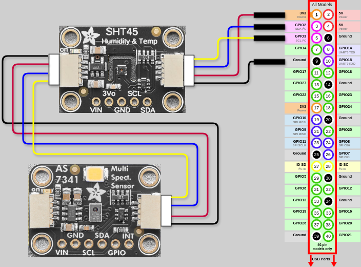
Using the STEMMA QT cable, connect the Adafruit AS7341 light sensor to the Adafruit SHT45 air temperature and humidity sensor. It doesn't matter which of the two ports on the sensors are used.
Then, connect the STEMMA QT to JST SH 4-pin cable to the final port on the Adafruit SHT45.
Power off first
Make sure the Raspberry Pi 5 is POWERED OFF before connecting anything to the GPIO header.
Connect the 4 JST pins of the STEMMA QT to JST SH 4-pin cable to the Raspberry Pi's GPIO pins (pin layout), depending on their color:
| GPIO Pin | Wire color |
|---|---|
| Pin 1 | Red |
| Pin 3 | Blue |
| Pin 5 | Yellow |
| Pin 9 | Black |
Create the RS485 bus
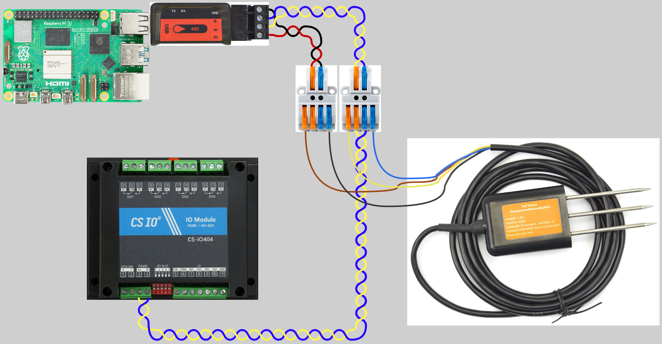
Both the DF-Robot soil sensor and the CS-IO404 relay connect to the Raspberry Pi via an RS485 bus wire pair. This bus wire pair is the primary way to connect reliable peripherals to the plant controller.
Measure out how far away you want the relay from the Raspberry Pi, taking into account that the 12V DC for the pump and relay must be connected near the relay, and that the pump will be getting its power from the relay. Take this length and multiply it by 1.5 for some slack — this will be the length of the RS485 bus. As a minimum though, it should be at least 50 cm.
Take two lengths of insulated wire, one blue, the other yellow, cutting each to be the length of the bus. Then, twist them together, tightly. (A cordless drill is handy for this.)
Then, take two more lengths of insulated wire, one red, one black, cutting them to be about 20 cm. Also twist these together, tightly.
Now, strip one end of each of the four wires, about 11 mm.
Connect these stripped wires to the USB to RS485 module, dependent on color:
| Terminal | Wire color |
|---|---|
| GND | Black |
| B- | Blue |
| A+ | Yellow |
| 5V | Red |
With both twisted pairs connected to the USB to RS485 module, lay them out side by side, and cut the yellow and blue pair so it is as long as the red and black pair. Put the remaining yellow and blue pair aside for later.
Strip the other ends of each of the four wires, again about 11 mm.
Take two 2 pole, 2-to-4 lever wire connectors.
Connect the yellow and blue wires to the 2-connection side of the first connector, blue to blue, yellow to orange.
Connect the red and black wires to the 2-connection side of the second connector, black to blue, red to orange.
Now, take the DF-Robot soil sensor. Connect it to the outer connectors of the 4-connector sides of the two lever wire connectors, depending on the sensor's connector wires:
| Sensor wire | Connector | Slot |
|---|---|---|
| Blue | First | Blue |
| Yellow | First | Orange |
| Black | Second | Blue |
| Red | Second | Orange |
With the soil sensor connected, strip both ends of the remaining yellow and blue wire pair that was previously set aside, again about 11 mm.
Connect one end to the remaining connections on the first lever wire connector, blue to blue, yellow to orange.
Connect the other end to the CS-IO404 4-channel relay module, yellow to the terminal labelled A+, blue to the terminal labelled B-.
Finally, plug the USB end of the USB to RS485 module into one of the Raspberry Pi's USB ports.
Note
If the total length of the RS485 bus line exceeds 200 meters or you are otherwise experiencing reading errors from RS485 connected sensors it might be necessary to terminate the lines with 120 Ohm resistors. To do this, simply connect two 120 Ohm resistors to each end of the line - one between the A+ and B- terminals on the USB to RS485 module and on between the A+ and B- terminals on the CS-IO404 4-channel relay module.
Set the MODBUS address of the CS-IO404 relay
All devices connected over RS485 MODBUS have an address or device id that identifies them. Usually, this is set to 1 as a factory default and must be changed during setup to avoid addressing conflicts between devices.
To change the address of the CS-IO404 relay, use the dipswitches on the front. These add to the address, dependent on their position — flipping the first switch on adds 1, flipping the second adds 2, flipping the third adds 4, flipping the fourth adds 8 and flipping the fifth adds 16.
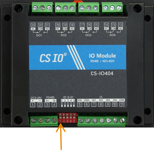
Flip the first switch (indicated in the image above) up to the "on" position. This will result in a MODBUS address of "2" for the CS-IO404.
Wire up the pump relay
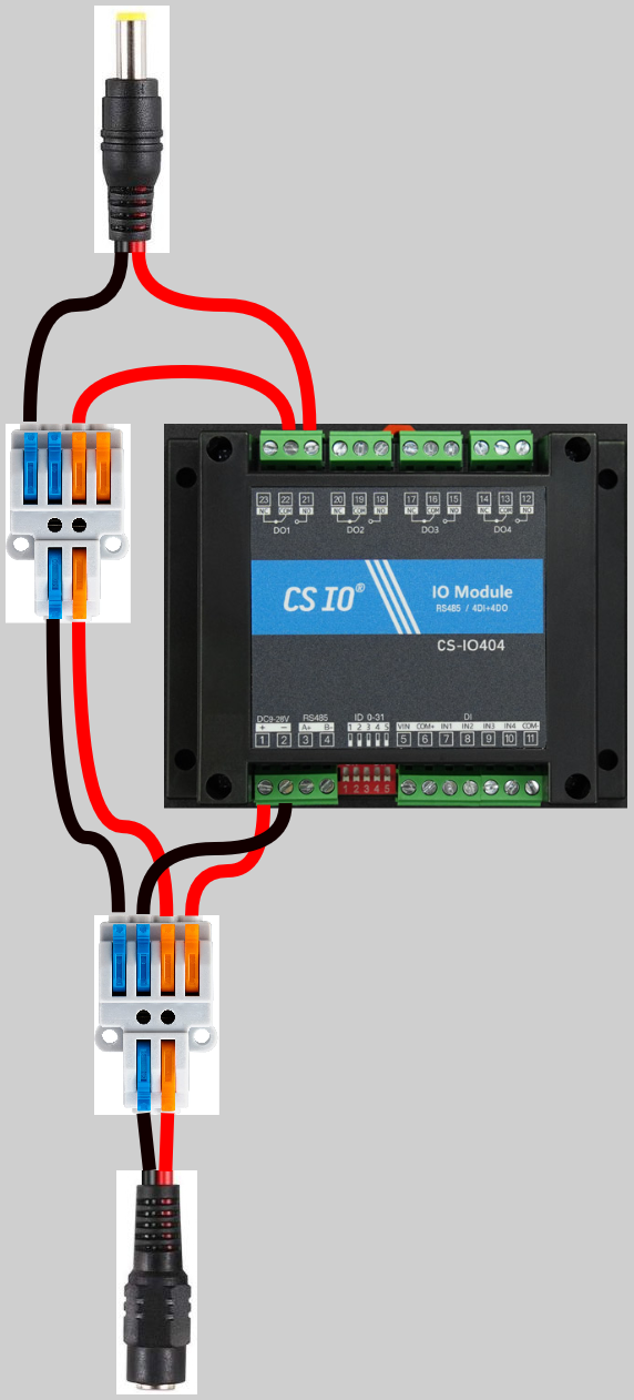
Take the 5.5/2.1 mm barrel socket and strip 11 mm off of the ends of the leads of the attached wires.
Connect these ends to the 2 connector side of a 2 pole, 2-to-4 lever wire connector, black to blue and red to orange.
Cut two short lengths of red and black wire, no more than 10 cm, and strip 11 mm off of each end of each wire. Connect one end of each wire to the 4 connector side of the lever wire connector, again black to blue and red to orange. Connect the other ends of the wires to the power terminals of the CS-IO404 relay, black to "-" and red to "+".
Cut a length of red and a length of black wire long enough that it reaches from the lever wire connector to about 4 cm beyond the opposite side of where the power terminals are on the CS-IO404 relay. Strip these wires in both ends, 11 mm, and connect one end of each wire to the last two connectors of the lever wire connector, again black to blue and red to orange.
Now take a new second 2 pole, 2-to-4 lever wire connector. Connect the other ends of the red and black wires to the 2 connector side, black to blue, red to orange.
Take a short length of red wire, strip the ends, and connect it between one of the orange connectors on the 4 connector side and the COM terminal of relay DO1 on the CS-IO404 (also denoted as port 22).
Finally, strip 11 mm off of the ends of the wires of a 5.5/2.1 mm barrel plug with 1 m leads, connect the red wire to the NO terminal of relay DO1 on the CS-IO404 (also denoted as port 21), and connect the black wire to the 4 connector side of the lever wire connector, black to blue.
Power is supplied to the CS-IO404 and the pump by connecting the 12V 1A power supply with 5.5/2.1 mm barrel plug connector to the barrel socket.
Connect the pump
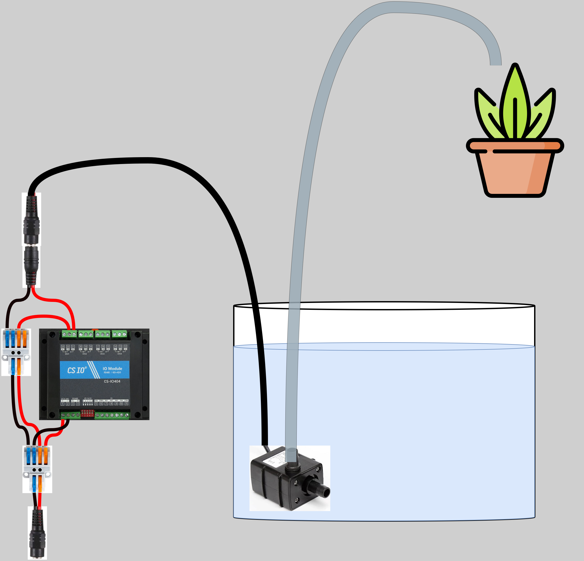
The AD20P-1230E submersible pump used for watering the connected plant is meant to be submersed in the system's water tank. This system assumes that the water tank and pump inlet is placed at a lower elevation than the plant, for example under the table that the plant is located on.
Place the watering tank in its final location with respect to the plant.
Measure the distance from the bottom of the tank to the plant, and add some extra slack. Cut some PVC tubing to this length.
Attach one end of the tubing to the outlet of the pump.
Fix the other end of the tubing above the soil of the connected plant (physical details of how are left as an exercise for the reader).
Connect the power socket of the pump to the barrel plug coming off of the CS-IO404 relay.
Finally, lower the pump into the tank and fill the tank with water.